Three Versions, One Solution!
In recent years, the demand for aluminum automotive parts in the die casting industry has been increasing. For die casting companies, higher quality demands of their customers lead to shorter development and production cycles for high-quality products. A small mountain full of tasks suddenly becomes Mount Everest. Survival is only possible for those who have the right tools at decisive moments.
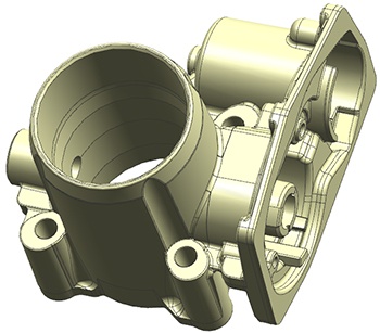
The Chinese company Guangdong Wencan Die Casting also had such a challenging project on its agenda. The goal: developing an electronic throttle valve using an aluminum die casting process.
Modern electronic throttle housings are among the key technologies for advanced vehicle control and safety systems to meet current and future CO2 emission regulations for internal combustion engines.
The customer had the following requirements for the component (see Fig. 1):
- Average wall thickness of 4 mm, max. 13 mm
- Pressure tight up to 3 bar, with a maximum leakage of 3 cm3/min. To meet this demand detailed specifications regarding porosity position and size as well as surface quality were required.
The above specifications for the casting do not only affect the quality of the cast part, the production efficiency, mold lifetime, trimming and the machining process, but also economic factors, such as yield and energy efficiency of the machine, must be taken into account.
In order to meet these demands in the shortest time possible, a virtual design of experiments with MAGMASOFT® was used.
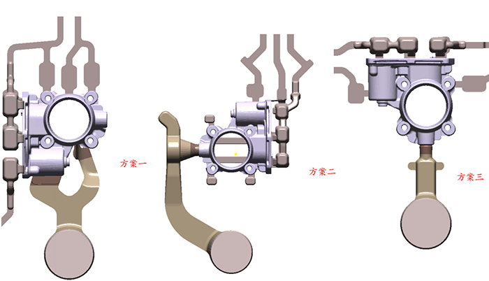
Three different gating and venting systems were designed, see Fig. 2.
Each casting system has different advantages and disadvantages:
Design 1 with two ingates and a relatively short flow path results in low temperature losses during filling and good feeding capabilities. The strong deflection of the melt at the runner and the associated high flow velocities may lead to die erosion. When the filling fronts from the two gates meet, there is also an increased risk of air entrapment. Due to its positioning, the gating area does not allow additional machining, which requires a very precise trimming.
Design 2 has only one ingate, which is located laterally in the throttle axle. This layout allows a runner with a smooth transition, preventing turbulences and thus air entrapment, oxides and other filling related defects in the casting. The ingate lies within the machining allowance, reducing the amount of trimming work. However, the relatively long flow path increases the risk of cold shuts and thus has also an unfavorable effect on the feeding.
Design 3 also has a single ingate located at the throttle axle, but with a different orientation of the component. This setup shows the shortest flow length. This leads to minimum temperature loss during filling, lower effort for trimming and a maximum feeding efficiency and yield. However, due to the short flow length, this layout has the disadvantage of being sensitive to dosing variations. This means that the position of the melt in the casting system may change so unfavorably at the time of piston acceleration that it leads to a significantly worse filling behavior.
Therefore, the engineers extended the virtual DoE (Design of Experiments) accordingly and analyzed the robustness with regard to the dosing variations. In order to display the dosing variations in MAGMASOFT®, the switchover point ('Switch Over Point') was varied in a range between 340 mm and 350 mm. Due to the specifications, the objectives of the DoE were a low-turbulence filling ('Smooth Filling') and minimal air entrapment ('Entrapped Air Mass') in the component.
Fig. 3 shows the influence of the switchover point at the end of filling for all three designs on the entrapped air mass. High air entrapment means a high risk of leakage.
The comparison clearly shows that design 2 (Version 2 and 5 in Fig. 3) has the lowest risk of leakage and is, moreover, robust to dosing variations (blue indicates low risk, yellow indicates high air entrapment).
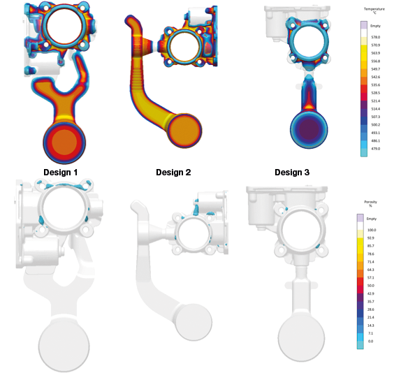
In a further step, the solidification behavior of the runners was compared (Fig 4). Here, the focus was on the point in time when the gate had completely solidified. From that moment on, further feeding of the casting by the pressure of the third phase became ineffective. Due to the short and solid gating, design 3 showed the lowest residual melt in the component and thus the lowest shrinkage porosity.
To safeguard the decision-making process, the tools of the Assessment Perspective in MAGMASOFT® were used:
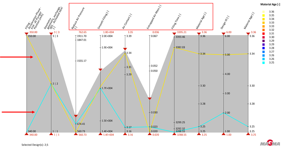
The parallel coordinate diagram (Fig. 5) shows the variables switchover point and gating design ('Gating Design‘) as well as all the quality criteria which were taken into account. It can be clearly seen that for variants 2 (blue curve) and 5 (yellow curve) the results for low-turbulence filling ('Smooth Filling') and air entrapment ('Reduce Air Pressure', 'Entrapped Air Mass') are very similar (see circles Fig. 5). From this, it can be deduced that the switchover point or dosing variations have only minor influence on the investigated criteria. The deviations in the further results are due to different mold filling times and are not significant for this analysis.
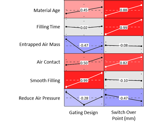
The main effect diagram integrated in MAGMASOFT® (Fig. 6) additionally shows the sensitivity of the two variables runner design and switchover point to the quality criteria investigated. The intensity of the red or blue color reflects the strength of the influence. It can be seen that the switchover point has almost no influence on the two quality criteria 'Smooth Filling' and 'Entrapped Air Mass', whereas the gate design influences almost all quality criteria to varying degrees. It is therefore obvious that 'Smooth Filling' reacts most strongly to the different gate variants.
Taking into account all the knowledge gained from the virtual analysis, Guangdong Wencan chose variant 2. It shows not only the lowest risk of leakage, but is also robust against dosing variations.
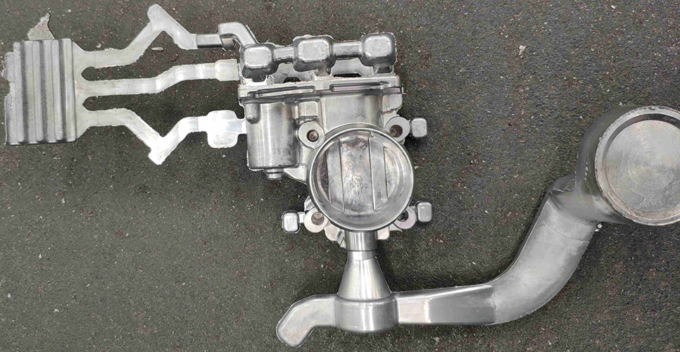
Figure 7 shows the housing produced with variant 2. The component surface shows no flow or visible defects. Thus, sampling could be started directly. The casting directly met all required specifications and even exceeded the customer’s quality requirements in the X-ray and leak tests.
Development time and costs were reduced and the product was smoothly transferred to mass production. It turns out: With the right tool, any challenge can be met and the mountain of tasks suddenly does not seem so huge anymore.
About Guangdong Wencan Die Casting
Guangdong Wencan Die Casting was founded in 1998. The company is mainly engaged in research and development as well as the production and sale of precision aluminum alloy die castings for the automotive industry. The company is headquartered in Foshan City, Guangdong Province, China.
