Creating Robust Processes with MAGMASOFT® and Expertise
Low-pressure die casting processes enable efficient production. The cavity is filled smoothly and homogeneously. This casting process can be highly automated while also offering foundries a high yield. Often, neither feeders nor machining allowances are necessary to produce dimensionally accurate castings. However, once the casting becomes more complex, the risk of porosity due to hot spots increases also in this process. Possible solutions are feeders, additional machining allowances and mold-related measures. Such approaches, however, reduce production efficiency. MAGMASOFT® helps the foundryman to manufacture efficiently, with optimum yield, improved energy efficiency and minimal scrap.
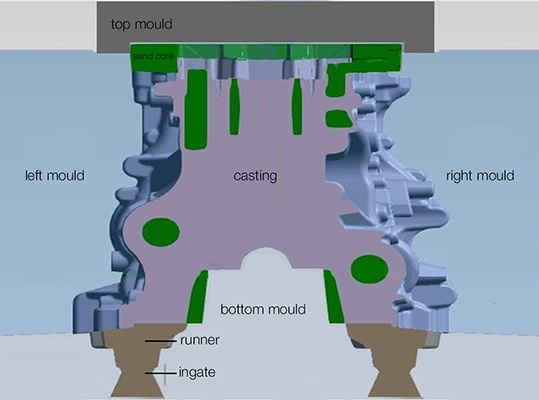
BMW Brilliance Automotive Ltd. (BBA) casts cylinder blocks (Fig. 1) from the aluminum alloy A356 using the automated LPDC process. Cylinder blocks require balance shafts to reduce engine vibrations. Balance shafts are mounted in balance shaft bores. To ensure that these are preformed directly during casting, BBA inserted sand cores in two places (marked in green in Fig. 1).
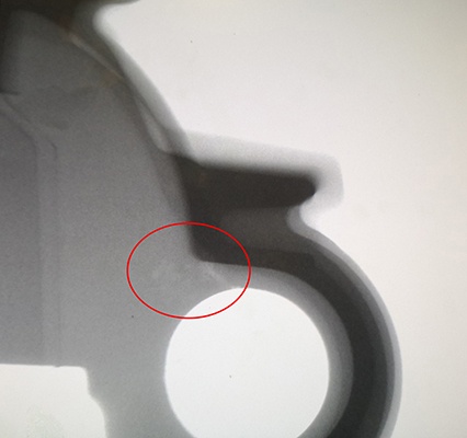
BBA’s engineers suspected this was causing casting defects in the sand core area: The wall thickness there was too thin to ensure adequate feeding, which resulted in hot spots forming during solidification. Therefore, they performed X-ray inspection on a finished prototype and found porosity above the right balance shaft bore (Fig. 2).
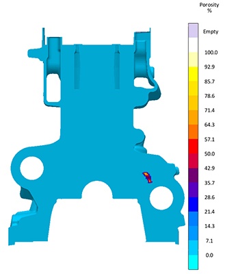
The experts calculated that the porosity would cause a scrap rate of at least 1 % and considerable, ongoing quality assurance effort. Too much for BBA. They then simulated the casting with MAGMASOFT® under real casting conditions of the prototype with the objective of eliminating the defect (Fig. 3). The simulation results revealed the hot spot that led to porosity. Could it be eliminated?
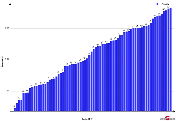
BBA specified that the process should remain both resource and energy efficient. Therefore, under these conditions, feeders did not apply as a solution so as not to reduce the yield. Possible solutions were to adjust the temperature of the melt, the heating temperature of the mold and the start time of the cooling on the right side core and bottom mold without affecting the energy balance. With MAGMASOFT®, the engineers combined these casting parameters, calculated 72 feasible variants, evaluated and sorted them based on the porosity level: It is lowest for variant 36 (Fig. 4).
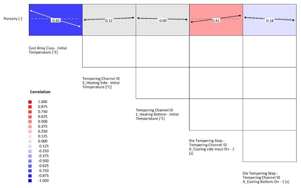
The main effect matrix (Figure 5) allowed evaluating the results more accurately. The engineers thus considered qualitative goals, such as cost-effectiveness and feasibility. They found that a higher temperature of the melt had the greatest effect: If the temperature rises, the porosity decreases considerably. Delaying the cooling or increasing the heating temperature of the bottom mold leads to a minor decrease in porosity. In contrast, the porosity increases when increasing the heating temperature of the right side core or delaying its cooling.
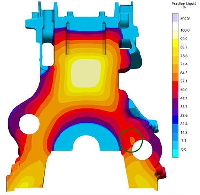
With these findings, the engineers first focused on the temperature of the melt and simulated the casting with a pouring temperature of 730 °C. The right side core is cooled for 200 seconds as soon as the melt reaches the gate. According to the calculation, these parameters should cut the scrap by half. However, this was still not enough for the engineers. Therefore, they looked for further possibilities for improvement. One approach they found was the ‘Fraction Liquid’ result 2 minutes after filling. At this point, an isolated zone of residual melt forms above the right-hand balance shaft bore (Fig. 6, marked green).
However, the sand core used there impedes the feeding, so that the critical area cannot be fed. By widening the feeding path, the critical area is sufficiently fed, thus preventing the defect. The foundrymen suggested reducing the size of the sand core to increase the feeding capacity.
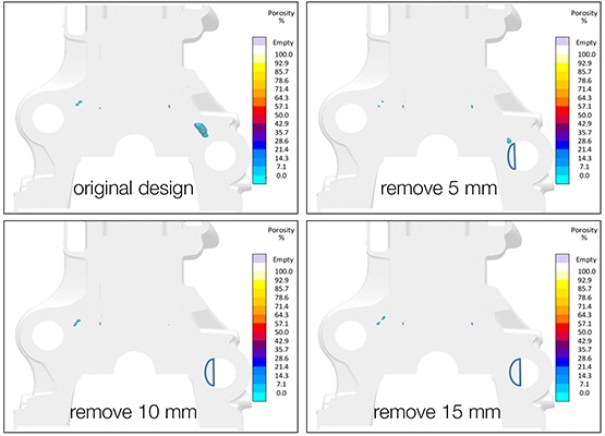
MAGMASOFT® was used to remove successively three segments, 5, 10 and 15 mm wide respectively, from the left half of the sand core (Fig. 7) and simulate the solidification accordingly: When removing a 10 mm wide circle segment from the sand core, this should increase the feeding path and eliminate porosity in the casting. Problem solved, right? The machinist noted that the asymmetrical borehole applied uneven stress to the machining tool, leading to a too high wear of the tooling.
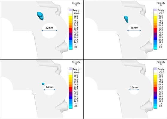
He suggested adjusting the diameter of the balance shaft bore (Fig. 8) and thus applying a uniform stress to the machining tool. Originally, the diameter was 36.5 mm. The engineers simulated the casting with diameters of 32, 28, 24 and 20 mm: For a sand core diameter of 28 mm, porosity was reduced by one third and disappeared completely at 20 mm. A diameter of 20 or 24 mm would require a more time-consuming machining process. At the same time, the stability of the right core would decrease with these diameters. If the core broke, this, in turn, would produce scrap. A diameter of 28 mm would be a good compromise: The additional machining effort would be acceptable while also ensuring core stability.
BBA tested this design in an initial batch of 100 cylinder blocks. X-ray photography after casting revealed: They were all free from defects. In a second batch, BBA poured 1000 units. Those, too, did not show any defects. The results were suitable for series production. Scrap was minimal due to the adjusted parameters and design changes, without significantly reducing the yield or noticeably increasing energy consumption.
Even in low pressure die casting processes, it is not always possible to prevent typical casting defects, such as porosity. In problem cases, MAGMASOFT® users adjust casting parameters and casting system design or even casting geometry. Foundries thus not only avoid scrap, but also benefit from processtypical advantages, such as balanced filling, high yield and process automation. Ultimately, MAGMASOFT® and the experience of foundrymen complement each other: MAGMASOFT® makes it possible to follow up on foundrymen’s ideas autonomously, promptly and economically, thus finding the best solution for the production process – all this without requiring expensive and time-consuming trial and error.
About BMW Brilliance Automotive Ltd. (BBA)
BMW Brilliance Automotive Ltd. (BBA) was founded in 2003 as a joint venture between BMW and the Brilliance Group. BBA is active in the fields of R&D, purchasing, production, sales and customer service, and has a production facility in Shenyang and subsidiaries in both Beijing and Shanghai. The company has recently substantially reduced its CO2 emissions as well as the energy and water consumption per vehicle produced.
